MATHEWS BRIDGE IMPACT EMERGENCY RESPONSE STORY

MATHEWS BRIDGE IMPACT EMERGENCY RESPONSE STORY
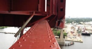
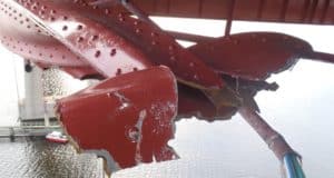
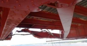
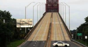
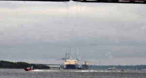
On the afternoon of Thursday, September 26th, at around 2:15pm, a non-commissioned United States Naval Ship struck the north bottom truss chord of the Mathews Bridge while under tow and on its way to the North Florida Shipyard. The ship’s stern ramp was in the upright position and the port-side ramp buttress did not clear the bridge’s lower chord. Because all but the ship’s stern ramp had already passed beneath the bridge, the momentum was too great to overcome and the north lower chord of the bridge was severed. Traffic, both on top of and below the bridge, was shut down immediately.
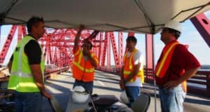
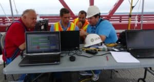
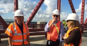
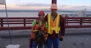
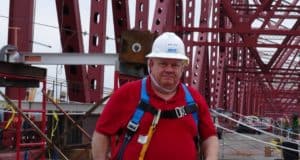
June 29 2014 Interview – Watts, Sturm, Haney, & Me
Click on any of the topics below to learn more about the impact and repair project.
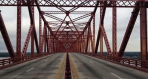
This impact occurred in the main channel span of the bridge which spans 810’ between pier supports. In the center of that span is a 340’ long “drop-in” section designed to hang with pin-and-hangers between two end segments that are cantilevered off the piers. This configuration results in the center section being “simply supported” which essentially means that the top chord carries compression forces and the bottom chord carries tension forces (similar to the top and bottom a simply supported beam).
Given that the bottom chord carries tension forces, the impact resulted in the chord pulling apart and sagging, analogous to cutting a taunt cable. With only two tension chords, one along the north truss line and one along the south truss line, these members are considered “fracture critical” due to a lack of redundancy (meaning the loss of one would likely result in system failure). Based on computer modeling and field observation, it was surmised that the floor system was stiff enough to re-distribute the loads locally to other members of the bridge. While this re-distribution of load did keep the span from collapsing, it also induced extra stresses in members that were not designed to carry these added dead loads; and most certainly not the significant additional live load produced by vehicle traffic.
With all of this, the challenge faced by the FDOT and its team was how to pull the ends of the severed chord back into position, relieving stresses elsewhere, and hold the chord ends in place temporarily while performing permanent repairs to the damaged members – with the ultimate goal of restoring the safe load carrying capacity of the bridge.
The Mathews Bridge is one of the main corridors feeding the business community and residents in the heart of the City of Jacksonville. It is also a major evacuation route during hurricanes and other declared emergencies. With a traffic volume of approximately 56,000 vehicles per day, the Mathews Bridge is a vital emergency and economic lifeline to the city.
It also carries one of the main routes to major sporting and recreational venues such as EverBank Field (home to the NFL Jacksonville Jaguars, the Florida-Georgia Football Game and the Gator Bowl), the Sun’s baseball field, the Fair Grounds, the Arena, and Metro Park. Reestablishing this vital link to downtown in the shortest possible time was key to minimizing economic impacts. Of specific concern was the looming Florida-Georgia football game scheduled for Nov 2. This major event attracts football fans and “tail-gators”, many of whom homestead in RV City at the base of the bridge for the week before and after the event. Also of concern was the NFL Jaguars scheduled home games and multiple cultural events scheduled during the month of October.

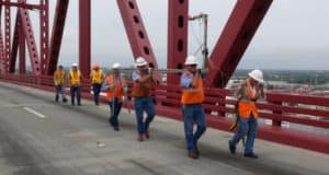
By 6:00pm on the evening of the impact an initial assessment team was loaded up in an FDOT vehicle convoy and headed to the bridge to inspect the damage in person. The team consisted of FDOT engineers lead by Will Watts with Bryan Sturm and myself from Reynolds, Smith & Hills (RS&H). We worked into the night taking photos and documenting the extent of the damage so that 1) a global stability evaluation could be made and 2) the design effort could get underway immediately.
Within 76 hours of impact, a bid package was prepared for potential contractors. The package contained a written agreement, scope of work, sequence of construction, and repair plans for both temporary and permanent repairs. Producing a deliverable of this magnitude in such a short period of time was only made possible through the substantial effort of a dedicated team working day, night and through the weekend.
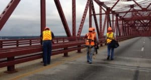
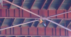
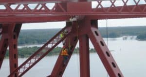
Beginning at dawn the day after impact, climbing inspectors from Burgess & Niple (B&N) and myself began combing the bridge, identifying and documenting areas of concern and listing repair needs. At the same time, a design team of engineers (from FDOT, RS&H, B&N, and Hardesty and Hanover (H&H)) brainstorming ideas for temporary and permanent repairs, evaluating the proposed concepts using an RS&H computer model and other design tools, and finalizing the construction sequence and repair solutions. Meanwhile, a team of production engineers lead by the late (and great) Dick Wallace was translating the design team’s ideas into final plan sheets. Additionally, a third team composed of FDOT D2 personnel were developing and ironing out the contract language and composing the bid package. The package was delivered to potential contractors by 6:30 Sunday evening. Contract and scheduling highlights include:
- 40 calendar day contract time with an incentive/disincentive of $50,000 per day
- 24 hour, seven days a week effort required with no weather days or holidays granted
- A total weight limit of 5 tons in the suspended span prior to the completion of temporary repairs
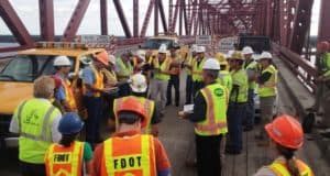
- Mandatory pre-bid meeting on-site at 10:00am, Monday 9/30
- Contractor Bids Due by 2:00pm, Tuesday 10/1
- Of the five Contractors that attended the pre-bid meeting, three submitted bids and Superior Construction was the successful bidder, with a bid of 1.07M.
- Pre-Construction meeting was held within hours of the Superior win announcement
- Florida Structural Steel (FSS) was chosen to perform the steel fabrication
- Contractor to begin work on the bridge on Wednesday, 10/2 (Contract Day 1)
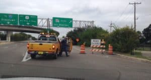
The Jacksonville Sheriff’s Office (JSO) responded to the initial impact immediately and closed the bridge before something catastrophic could happen and continued their support throughout the duration of the bridge shut-down. River traffic was also shut down under the bridge immediately after impact until the an assessment was made that the bridge was deemed stable under its own weight. The US Coast Guard was an instrumental partner in the initial response but also throughout the duration for work that was performed over water.
Enough cannot be said regarding the response of our industry partners within moments of the event. Industry contractors located just north of the base of the bridge, provided access to engineers and others responding to damage assessment. The existing construction contractor, Intech Contracting, mobilized crews (within an hour) to uncover detour route signs prior to rush hour traffic. Contractors working on other nearby FDOT projects, “stepped down” from previously scheduled work activities, including lane closures, allowing for full utilization of alternate routes in and out of town.
To meet all of the challenges being faced, the Department quickly mobilized all available resources. This unprecedented collaboration and team effort led to an extraordinary degree of cooperation between consultant & FDOT design engineers, consultant & FDOT project engineers; construction personnel; administrative personnel, structural engineers, bridge inspectors, law enforcement officers, producers, shippers, fabricators, specialty engineers, and public information personnel. All of the project personnel had to be diverted from their original projects, straining the schedules and the staff that remained. Professionals put personal lives on hold while working grueling schedules, often seven days per week.
The overwhelming response from the community was “do what you have to do to make the bridge safe”.
Daily updates including key milestones and goals were provided to the FDOT Public Information Office for distribution to the media. Through the immediate and constant flow of information, public outreach, and continued support from local public officials, the public bought into the uncomfortable yet necessary inconvenience of the situation. Efforts were made to explain, show, and educate folks to the challenges faced by the repair team. Those challenges included concerns regarding the loads the bridge could handle, limitations with equipment, safety concerns with workers in the wind, rain, being 150’ in the air above water, etc.
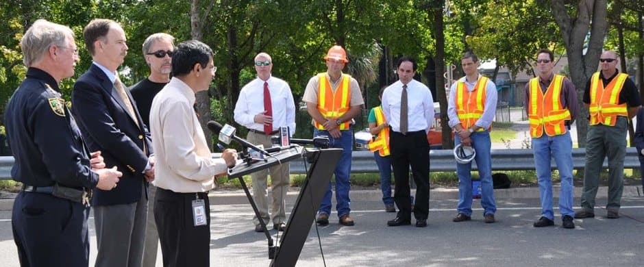
Intelligent Transportation System (ITS) support notified motorists and the traveling public of bridge closure and suggested alternative routes. The internet and social media was utilized to post progress updates, and coordinate with local and regional leaders. The press visited the site on multiple occasions and FDOT Secretary Ananth Prasad held an on-site press conferences. To further minimize impacts, construction projects on major detour routes to downtown were halted and closed lanes were opened to provide additional capacity and reduce travel times during rush hour. The Traffic Management Center worked directly with Jacksonville Sheriff Office and media outlets to provide constant traffic updates.
????????????????????????????????????
(Days in parentheses reflect contract days)
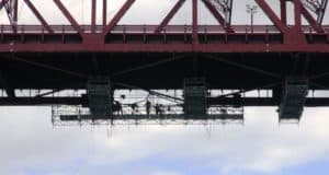
1. Installation of scaffolding below deck (First scaffolding in place on Day 3)
The below deck scaffolding segments were barged in and cable hoisted into place. Due to the load restrictions imposed by the contract, the installation occurred in phases, with a minimal footprint prior to temporary repairs.
2. Install strong backs and saddle beams (Day 5-7)
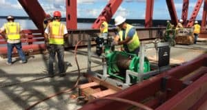
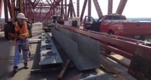
A pair of wide flange beams was positioned such that they were anchored to the east cantilever span, supported at the finger joint (fulcrum) and extended out over the floorbeam east of the impact. The idea was to saddle it using rods through core holes in the deck and jack up the beam to relieve some of the vertical force imposed to the north truss in that critical location – to assist in geometry restoration. The strong backs were fabricated by FSS, located in Tampa, and trucked to the bridge on Saturday October 5th. Because the beams were 70’ long, transporting them required an Overweight/Overdimensional Permit and Florida Highway Patrol (FHP) Escort. Orchestrating this event in such a rushed timeframe took considerable coordination between multiple FDOT offices, FSS, and two FHP troops. Upon arrival, positioning the strongbacks was a challenge due to the load restriction on the bridge. Instead of craning them into place, a cable pulley system was devised to roll them into position along high strength dollies.
3. Cut and removal of the damaged chord (Day 6-8)
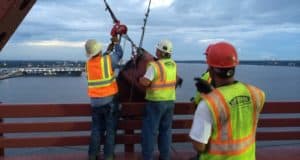
The damaged chord was cut and removed, one three foot section at a time. The sections were hoisted over the bridge railing, documented, and trucked to the FDOT Maintenance Yard for further investigation.
4. Installation of the temporary lower chord (Day 9-13)
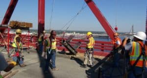
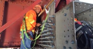
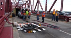
The temporary lower chord consisted of four, 66’ long, 1-3/4” diameter high strength threaded rods (150 KSI) with spherical nuts. Fortress anchors for the rods were bolted to the lower chord beyond the limits of the damaged area, with the use of nearly 100 high strength bolts. The fortresses and rods had to be hand handled and positioned into place using manpower and pulley systems rigged above the deck. This was quite a challenge; given that one half of a single fortress weighed about 2,200lbs.
5. Tensioning of temporary lower chord (Day 13-17)
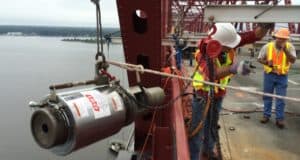
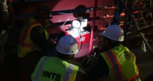
The jacking process was done incrementally over a five day period with increasing bar loads at each stage and a final collective load of 780 kips. A 100 ton jack was used to tension each of the four bars in-turn. The initial tensioning, on the evening of Monday, October 14th yielded stubborn results. The hope was that the gap created by the severing of the tension chord would start to close, but the measured closure after final jacking that night was approximately 1/16” longitudinally – much less than anticipated. Heads were hanging low by the end of that evening and concern was starting to mount regarding the repair strategy. Lift off forces were taken the next day and it was found that the bars had relaxed quite substantially. Over the next four days, a series of jacking phases followed by bar relaxation resulted in much more encouraging numbers and by the fifth day, the longitudinal and vertical geometry of the bridge had been restored, including a nearly perfect restoration of the floor beams from their swept position back to a normal alignment. Survey points and strain gages placed in various locations on the bridge were monitored closely during each tensioning process.
6. Additional truss member repairs (Continuous)
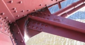
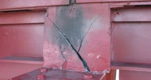
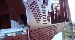
The lower chord replacement was the primary focus of the job, but there were other damaged elements that needed attention as well. The immediate loss of capacity in the lower chord caused the tension force to transfer to and overload the lower later bracing. The north bracing member immediately failed and tore out (block shear failure) from a gusset plate connection. With the failure of the chord and brace, the impact buckled one of the bottom lower lateral gusset plate. All of these members were replaced. Nearby floorbeams were swept out of alignment. This deformation was corrected during the tensioning process. The impact also caused bowing of a set of the upper chord gusset plates which were stiffened with steel angles. Other miscellaneous needs, such as rivet replacements were addressed.
7. Heat straightening process (Day 15-19)
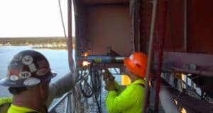
In order to receive the new chord, the gusset plates at both ends of the connection required heat straightening. This process resembles art more than science as it entails alternate cycles of heating and forming while staying within very strict limits of temperature and force ranges. The heat straightening team (International Straightening Inc.) used an oxy-acetylene torch with porta-power hydraulics and custom made jigs to apply up to 8,000psi without force cold bending of the steel. Heat was applied at up to 1200°F for no more than a minute at a time while keeping constant movement with the torch. The effort took approximately 100 man hours.
8. Installation of stub beam at the west connection (Day 19-22)
Given the extent of the heat straightening required of the gussets and fill plates at the west lower chord connection, and the expectation of a tricky fit-up as a result, FDOT Central Office (CO) recommended to first install a short stub beam to extend eastward from the connection, and then splice the new lower chord to it, as opposed to trying to connect the lower chord itself directly to the panel point.
9. Splice new chord between the new stub beam and the existing chord stub end (Day 22-25)
The replacement lower chord was trucked in from FSS in one complete built up section, but once on-site, it was dismantled and installed piece by piece and then bolted together in final position. These steps were necessary because lifting the entire 8,000lb chord and booming out horizontally nearly 40’ from the eastbound lanes would have overloaded the boom truck and been more difficult to weave through the truss members to set in place.
10. Installation of “cheese fill plate” & cover plate (Day 24-25)
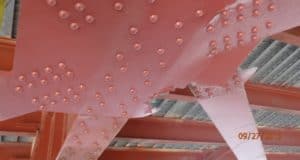
Due to the large plastic distortions of the existing outside impacted gusset plate, the team received direction from CO to use a “double-bolt and cheese filler plate method” to add an outside cover plate to the existing connection for the purpose of strengthening it. This method proved very valuable because not only did it strengthen the connection, but it accomplished this without the need to remove the existing gusset plate which would have required removal of all of the existing rivets at once, thus “unzipping” the entire connection. Instead, each rivet that was removed was immediately replaced with a long bolt and nut. The cheese fill plate was then installed with holes large enough to fit around the nuts and then finally, the cover plate was added and bolted in place with a second set of nuts.
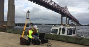
One of the larger challenges of the entire project was how to fabricate the fill plate and the gusset cover plate such that the required 199 bolt hole locations would align with the holes in the existing gusset plate. Essentially – how do you accurately make a template from a 7’x6’ plate that must remain in place on the side of a bridge? The answer was to use the on-site surveyor’s laser scanner which is a $130K 3D infrared high-speed, high resolution piece of equipment with short range accuracy of 0.5mm. To make it happen, Will Watts directed the District 2 Bridge Maintenance crew to build a bracket that would attach to the side of the bridge and extend out to hold the scanner eight feet away so that it could do a full scan of the existing gusset plate. The scan was then transferred to CADD and used by the fabricator to fabricate the plates.
11. De-tension temporary chord and remove fortresses, rods, scaffolding, and construction equipment (Day 26-27)
Once the new chord was in place, the remainder of the effort included de-tensioning the temporary chord, removing the rods and fortresses, installing cover plates on the lower chord webs at the fortress locations, and removing the scaffolding from under the bridge and the construction equipment from atop the bridge.
Strain gages were installed on the bridge in order to monitor both the re-distribution of forces during the jacking process as well as the material response of specific members during de-tensioning (restoration of the bridge), load testing, and after the bridge was opened to traffic.
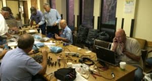
The installation process was quite an undertaking and required a team of people with various backgrounds to get it all done. The process began almost immediately after the impact, as conversations between the design group and strain gage support team (AMEC, Bartlett Engineering, and BureauVeritas) were underway in order to make determinations as to where the gages would go, how many were needed, where to obtain the materials, and how they would be installed.
The gages used for this installation were bondable foil strain gages. A strain gage uses the principle that the resistance of metal increases when stretched, and decreases when compressed. Because this response is weak and strain gages must be small to measure the strain at a spot, each gage uses a 5 inch long by 0.002 inch wide foil “wire” that is, in effect, folded to create a grid that is only 1/4 inch long. Each tiny delicate gage was pre-epoxied to a stainless steel shim and a “pig tail” was pre-soldered to the gage so that the gage only needed to be plugged in. The pre-fabrication of these set-ups was accomplished by the D2 Bridge Maintenance crew working 7 days a week for no less than 12 hours a day.
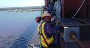
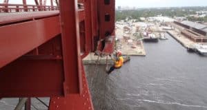
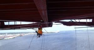
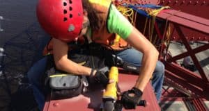
The installation of the gages was performed by Bartlett engineers and engineer climbers from B&N and RS&H, while on-rope. The installation of a strain gage was no easy task. The location had to be precisely laid out and recorded, the area carefully prepared with just the right surface finish using an electric grinder followed by hand finishing, and then the gage was welded in place and then waterproofed. The welding of each gage required approximately 100 microscopic welds in a specific pattern of two rows around the edge of this “finger nail” sized shim without damaging the delicate folded foil wire that covers its center. Over the entire bridge the climbers performed over 14,000 of these tiny spot welds, to install 140 plus gages. Additionally, about 13 miles of wire was run along the bridge members to meet up at the central data acquisition system (DAQ) located on top of the east pier, under the bridge deck. The DAQ system was controlled by a computer, also located on the pier cap. The computer was in turn wirelessly controlled and monitored using a cellular technology “hot spot” that allows project team members to view and control the bridge computer from anywhere.
SURVEYING
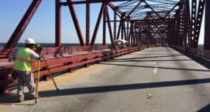
From the day after the impact, through to the opening of the bridge, surveying effort was a daily occurrence. During the first week, D2 Bridge Inspectors surveyed positions along the deck to watch for signs of continual creep. Additionally, survey data gathered by Arc Surveying & Mapping was monitored at the following locations:
- The top of deck was surveyed at four positions across the width of the bridge at each panel point (33’-9” apart) for 810 feet between the piers. This survey was performed with a digital level which uses a digital pulse and a bar coded staff. This type of level is more accurate than traditional ones because it removes the error inherent with human interpolation of staff gradation.
- The floor beam bottom flanges were surveyed at each end of each beam between the main channel piers using a 3D laser scanner and reflective targets affixed to the beams themselves. This piece of equipment can produce results up to a thousand times more accurate than a conventional total station while also eliminating human error.
- Reflective targets were set above the deck between panel points 19’ and 22’ on both truss lines to a) verify the 33’-9” center-to-center panel point distance and to b) monitor, during the tensioning process, the reduction in length along the north truss between 21’ and 20’ (impact zone) as it closed in longitudinally from the open gap back down to 33’-9”, its original condition.
This survey data was monitored and graphed on a daily basis. The total measured horizontal correction was 3- 5/8” and the total vertical correction was 2-13/16”.
LOAD TESTING
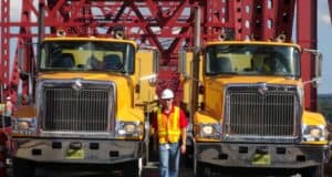
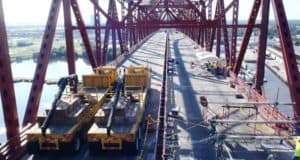
Load tests were performed at two stages during the project: after completion of temporary repairs and after completion of permanent repairs. The tests were performed using two FDOT flat bed trucks, weighing 48,000 pounds each (unloaded). To load test the bridge, concrete blocks, weighing 2,000 pounds each, were stacked on top of the truck beds and then the trucks were driven over the bridge while making three stops along the way. The first two stops positioned the truck axles specifically to localize the load over the damaged areas (Panel Points 21’ and 20’) and the third was positioned more globally to maximize load to the upper and lower chords and to look at overall behavior. During each event, four tests were performed using two trucks side by side, each time with increasing load. The loading sequences were as follows:
Post Temp. Repairs: Empty – 12 Blocks – 18 Blocks – 24 Blocks (max load = (2) HS-25 equiv. trucks)
Post Final Repairs: 12 Blocks – 24 Blocks – 30 Blocks – 36 Blocks (max load = (2) FL-120 equiv. trucks)
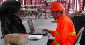
Only the eastbound lanes were loaded during the first set of load tests and both directions were loaded during the final set of load tests. (Lane loads cannot be accurately load tested). During all of these tests, the bridge’s response was monitored on-site with a laptop computer wirelessly communicating with the strain gage data collection hub located on top of the east channel pier. Mobilization of the trucks, execution of the load tests, and analysis of the strain gage data were all coordinated by the FDOT State Structures Research Office.
The project met its intended goals by restoring the structural integrity of the bridge and opening to traffic in record time. Using innovative techniques and a team of professionals working 24/7, a project that normally would have taken over a year to design and construct was completed in only thirty-three (33) days. Permanent repairs were completed on Contract Day 26, just 31 days after impact. The bridge was open to traffic on Tuesday, October 29th at 5:30am – 12 days ahead of schedule. This could only be accomplished by the dedication of nearly 200 professionals working round the clock to restore the bridge safely.
When all was said and done, nearly 20,000 pounds of permanent steel was replaced and over 1,000 bolts were installed. Considering the challenges posed by the severity of the damage, weather, and a multitude of complex aspects – design, plans production, shop drawing process, steel fabrication, material delivery, temporary chord placement, tensioning stages, heat straightening, member repair and removal, strain gage installation, and load testing – it should be considered an amazing accomplishment for all involved. The successful completion of this emergency response project, ahead of schedule, serves to demonstrate what focused, seamless, and collaborative effort by a dedicated team of individuals can do.
By restoring the integrity of the bridge and completing the project ahead of schedule, the community realized a projected Road User Cost savings of $7,224,420. Further, by completing the project ahead of schedule, economic impacts to the Florida/Georgia Game, specifically for the day of the event, were avoided. This generated tremendous appreciation from local officials and the public.

OLYMPUS DIGITAL CAMERA
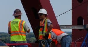
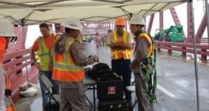
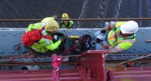
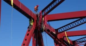
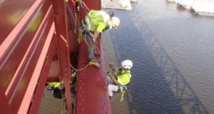
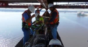
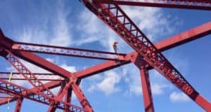
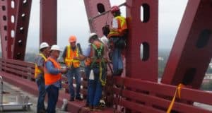
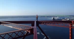
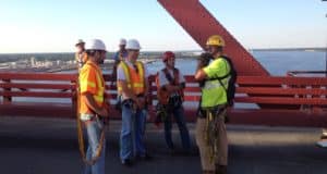
When the impact occurred, I was fortunately still an employee of RS&H and was involved throughout the entire process – from initial assessment to bridge opening. It was an extremely rewarding and fulfilling experience as I was able to play a supporting role in many aspects of the project. I was a member of the first response team that went out to the bridge right after the impact to perform an initial damage assessment and then assisted in the development of the scope and contract plans. Alongside Burgess & Niple inspection engineers, I provided on-site assistance for the duration of the project including using rope access techniques to: perform hours of inspection, install strain gages, assist pin testers in testing upper chord pins, assist surveyors in target installation and data monitoring, assist fabricators and the contractor by taking field measurements for temporary and permanent replacement members, and assist Will Watts and the FDOT maintenance crew with many miscellaneous tasks.
It was an honor to be a part of such a dedicated team of individuals who had the same goal in mind – to repair the bridge as quickly and as safely as possible. I really appreciate the leadership of RS&H during the project. They supported us in every possible way, providing us with resources and encouragement, and seeing to it that our other responsibilities were handled and off our plates so that we could stay focused. I appreciate the leadership at FDOT and specifically that of Will Watts. As the man in charge, he carried a lot of pressure and responsibility on his shoulders and he handled that charge with such poise and confidence – which the rest of us heavily relied on for assurance and to stay on track.
Lastly, I’d like to thank my friend and mentor, the late Mr. Dick Wallace. As an RS&H senior associate, Dick played a crucial role in the beginning of the project by participating in the design concepts brainstorming sessions, heading the repair plans drafting effort, and heavily contributing to the shop drawing review process. Mr. Wallace passed away in early December, just over a month after the bridge was reopened. He was very well known in the bridge community and is sorely missed by us all.
The project has received the following awards:
- Florida Transportation Commission – Excellence in Production of Work
- American Public Works Association Local
- APWA State
- APWA National
- ASHE – Eweek Award
- FICE/FDOT Outstanding Project Award
- ITE Transportation Achievement Award, Facilities Category
- FTBA Best in Construction Awards

LOCATION
FIT Engineering
219 NW Melanie Way
Lake City, FL 32055
PHONE
(904) 716-8367
